BMW 801 Fuel Injection Pump
The BMW 801 was Germany's most powerful radial
engine throughout WW II when one does not consider the BMW 803 which never actually left
its prototype stadium. With 14 cylinders arranged in two rows and 41.8 liters of cubic
capacity, it developed - depending on the version - between 1600 and 2000 hp. Bore and
stroke were each 156 mm, the compression ratio ranged between 6.5 (piston flat) and 7.2
(piston domed). The 2000 hp BMW 801 TJ fitted with a turbo supercharger for high altitudes
was installed in the Junkers Ju 388. Like most German aero
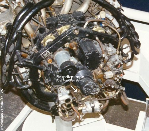
engines, the BMW 801 did not have a carburetor, but featured direct fuel injection. The
fuel injection equipment was of a new type, differing considerably from that employed on
the earlier BMW 132 engine. It was built by the Munich firm of Friedrich Deckel, which, in
times of peace, had best been known for the manufacture of the Compur shutter used on high
class cameras.
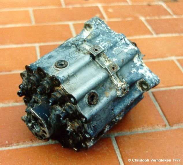 The pump unit is of cylindrical shape;
the fourteen individual pumping elements lying parallel to, and arranged concentrically
around, the longitudinal axis. Flange-mounted on the rear of
the engine (56 kB JPEG), the pumps are actuated by a three nosed cam driven through a
train of spur gears from the crankshaft at one-sixth engine speed. In the space enclosed
by the pumps is housed a fuel de-aerator.
The pump unit is of cylindrical shape;
the fourteen individual pumping elements lying parallel to, and arranged concentrically
around, the longitudinal axis. Flange-mounted on the rear of
the engine (56 kB JPEG), the pumps are actuated by a three nosed cam driven through a
train of spur gears from the crankshaft at one-sixth engine speed. In the space enclosed
by the pumps is housed a fuel de-aerator.
The fuel is supplied to a chamber in the rear end cover, from which tangentially-arranged
passages lead to an axially mounted tube projecting into the common fuel gallery for the
pumps. Fuel is swirled rapidly round the bore of the tube and passes into the gallery by
way of a series of holes in the periphery near the closed forward end of the tube. Air and
some fuel escapes by a small diameter axial nozzle in the rear end of the tube. The
discharge from this nozzle is controlled by a ported piston valve. When the engine is at
rest the valve is closed by a spring and thus the pump is maintained full of fuel ready
for start. The end of the piston valve is exposed to the fuel entry chamber, and, under
supply pressure, the valve is automatically opened against the constraint of the spring.
Pump barrels are an easy push fit in the housing and are frictionally secured about midway
of their length by a channel-section spring ring. Radial adjustment of the barrel to align
the ports for the datum setting is by a two pin spanner engaging holes in the top face. A
spring-loaded non return delivery valve drawn down by a sleeve-type nut against the top
face finally secures the barrel in its adjusted position. From the common gallery, fuel is
led to an annular space around the head of the barrel whence it reaches the interior by a
drilled intake port. Diametrically opposite, but at a slightly different level, is the
spill port. Injection is terminated on the delivery stroke when the uncovering of this
port by the plunger scroll relieves the pressure in the pump chamber and allows the fuel
to escape back to the annular space. Drillings in the wall of the barrel allow fuel from
the annular space to reach a groove in the bore of the barrel to ensure lubrication.
As a further precaution against air in the fuel lines, the annular spaces around the two
uppermost pump barrels, numbers 1 and 14, are connected by small diameter drilled passages
to the outlet from the de-aerator in order to bleed fuel and any air continuously from the
fuel gallery.
The pump plunger has a dual scroll to control the
duration of injection. It will be seen that any variation of the quantity of fuel
delivered affects both the commencement and the termination of the injection period, but
leaves the timing of the point of maximum delivery substantially constant. When, for
example, the delivery is increased, injection commences earlier and finishes later.
Control of this function is effected in the usual manner with a slotted sleeve floating on
the pump barrel and engaging the cross head on the stem of the plunger. For simultaneous
operation of the control, each sleeve is formed with a pinion and interconnected by a
circular rack which floats in a recess in the main body of the unit and is retained by the
overlapping edges of the plunger spring seating washers. These seating washers also
determine the longitudinal clearance of the sleeves against a washer placed over the
channel-section spring ring positioning the pump barrels. Backlash is taken up by a
torsion spring mounted on the outer diameter of each sleeve, with one end anchored in the
body and the other in the pinion.
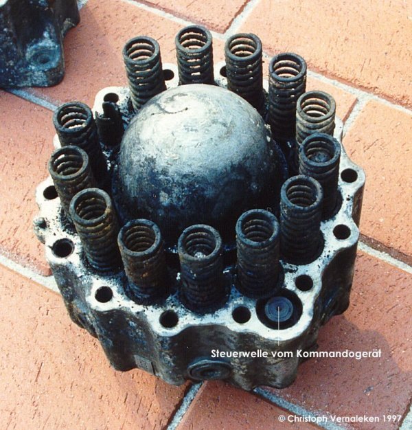
The springs visible in this picture of the front
part of the casing (taken shortly after the pump had been dismantled) push the pump
pistons back to their original position. The dome in the middle houses the de-aerator. The
control spindle (labeled "Steuerwelle vom Kommandogerät" in the picture above),
servo-operated from the automatic control unit, carries a pinion in engagement with the
sleeve of No. 4 cylinder. The width of this control pinion is reduced over a section of
its diameter to accommodate a pin mounted in the body. This pin defines the permissible
rotative moment of the pin, and in turn of the control sleeves of all the pumps, and also
prevents the torsional loading springs unwinding when the unit is detached from the engine
and the control mechanism is uncoupled.
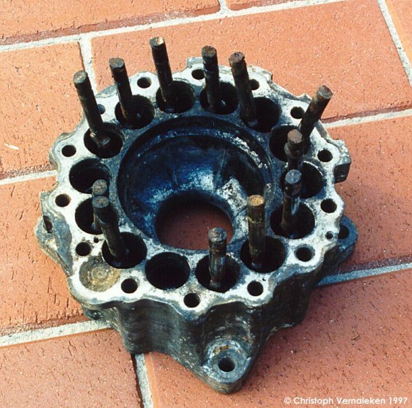
The rear part of the cast aluminum casing . The
pump pistons hang around loosely because they were not fixed vertically.
Continue...
Note: Most of the text of this article was taken from a
"Flight" article by F.C. Sheffield published in 1942.
© 29.12.2010 by Christoph Vernaleken. This article may not be published - as whole
or in excerpts - in any form without written permission of the author